

Darrell Egarr and Lucy Horton of MMI Engineering on a project to improve the design of sludge separation and collection systems.
In the UK, wastewater comprises domestic sewage and may contain industrial effluent, in addition to occasional run-off from surface water and ground water, which has infiltrated into the sewers.
The wastewater is ultimately discharged to a receiving water course such as a river. Legislation such as the European Urban Waste Water Treatment Directive, Bathing Waters Directive and Shellfish Directive mean that consent limits on pollutants are placed on the water companies by the regulator. If the consents are not met, the water companies are subject to fines.
There is currently a tightening of phosphorous consents (by up to one order of magnitude) and it is anticipated that, in the future, the consents may become even tighter. In order to meet these consents at Waste Water Treatment Works (WWTW), one method being pursued by water companies is the installation of mixing and flocculation tanks. According to a process engineer in one of the major UK water companies “there is no standard equipment for optimum dosing, mixing and flocculation”.
The use of Computational Fluid Dynamics allows multiphase systems to be assessed and the effect of design changes to be studied in order to optimise water treatment. Under an Innovate UK project, MMI Engineering has been collaborating with Leeds University and Sellafield Ltd on a project to improve the design of sludge separation and collection systems. MMI’s contribution to the project was the development of a framework within an open source Computational Fluid Dynamics solver that includes a population balance model, incorporating flocculation and breakup of particulates.
Flocculation
Flocculation is brought about by the collision of particles or flocs. There are three modes of flocculation. In this work, orthokinetic flocculation is considered to be the dominant mode, which is a function of the shear rate. The shear rate may be described by the scalar ‘G’, which is, in turn, related to the local turbulence in the flow. In addition to flocculation, floc breakup must also be considered, otherwise floc sizes would continually grow in a numerical model. Again, floc breakup models may also be a function of ‘G’ but also incorporate empirical constants that differ depending on the particulates. Thus, the effect of turbulence promotes flocculation but also induces floc breakup.
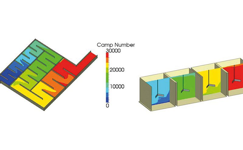
As flocculation requires particle collisions, the more collisions that occur, the greater the chance of flocculation. Thus, residence time, t, is also an important parameter. The product of ‘G’ and ‘t’ is known as the Camp number and values in the range 10,000 to 100,000 are quoted in literature [1] as being optimum for flocculation chambers.
Phases of development
In order to develop the flocculation solver, the physical models were implemented and tested in phases. These were:
1. Settling column to validate the model for settling.
2. Validation for convective transport against a lab scale settler.
3. Verification of population balance model against commercial CFD code.
4. Hypothetical test case for flocculation and breakup.
5. Validation of flocculation model against experimental data.
Hypothetical test case
To test the implementation of the flocculation and breakup models and to show the relative effects of two different systems, a hydraulic flocculator and a series of mixers were selected. The total volume of each was identical to achieve the same theoretical mean residence time for identical flowrates.
Figure 1 presents contours of the Camp number for the mechanical and hydraulic flocculators, for comparison, which shows that the Camp number at the outlet is around 30,000 in both cases. However, although the two systems performed the same in terms of Camp number, the particle size distributions at the outlet were very different, suggesting that other factors such as the shear rate, G, and the residence time distribution should also be considered when designing flocculators.
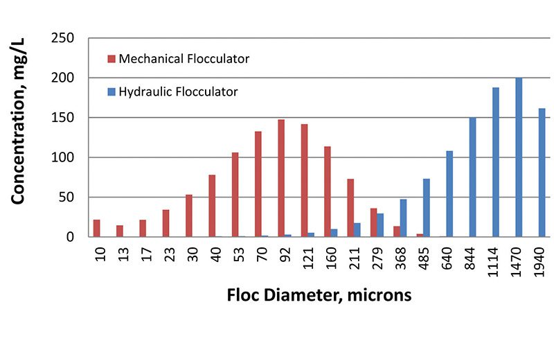
The results for the particle size distribution suggest that more breakup occurs in the mechanical flocculator compared to the hydraulic flocculator. This comparison is presented in Figure 2. The difference is evidenced by the size distribution being centred on a particle size of 92µm as opposed to 844 µm in the hydraulic flocculator.
The research programme has resulted in a solver that may be used to calculate flocculation processes. However, challenges remain in acquiring appropriate data, such as initial particle sizes, flocculation efficiency and other empirical constants that are required for the breakup model.
Dr. Darrell Egarr will deliver a presentation on the development of the flocculation solver at Aqua Enviro’s European Waste Water Management Conference (EWWM), 11-12 October 2016, Manchester Town Hall, UK. www.ewwmconference.com.
References
[1] S. Elmaleh and A. Jabbouri, “Flocculation Energy Requirement,” Water Research, vol. 25, no. 8, pp. 939 – 943, 1991.