
The humble storage tank remains a stubbornly profligate emissions source, even in this day and age, but this hasn’t gone unnoticed. Operators are coming under pressure like never before to get leakage issues sorted. The good news? A “comprehensive advisory infrastructure” is on hand – in the form of a set of tried and trusted industry standards. Envirotec asked tanks expert Assentech for tips on tightening up tank venting.

At a moment when minds are seemingly focused as never before on eliminating emissions from every sphere of human activity, however challenging, it’s reassuring to discover an area where much of the work seens to have been done – all that remains is to apply it, and that task is increasingly straightforward – even amenable to automation.
All the same, many tank owners and operators remain blithely unaware of the extent to which their assets are leaking vapour into the surrounding air, and in this situation it’s fair to say that ignorance is increasingly anything but bliss.
A weak link here seems to be the breather valve – often taking the form of a dual-port pressure/vacuum relief valve (PVRV) – a component that you’ll find located near the top of an atmospheric storage tank, and which performs the task of relieving excess pressure or vacuum when approaching design limits. This tends to happen in response to seasonal changes in conditions such as sunlight and rain.
Imperfect operation
The valve operates using a set of weighted, sprung or pilot-operated pallets: the air flow through the valve is controlled by the valve setting. A PVRV has separate pressure and vacuum ports which can be opened to relieve excessive pressure or vacuum but remain closed to the environment at all other times.
In an ideal world, this would be a tightly controlled mechanism, with a port being either open or closed, and ideally without any leakage occurring in the latter case. In practice, however, the valve will start to open gradually in advance of the set point being reached, allowing vapours to leak out. These vapours can be piped away for recovery but this is often too expensive or impractical to install. And even when the vent is closed, imperfect sealing often means vapour continues to leak out. These problems prevail across the spectrum of tank applications, even with tanks storing highly flammable, volatile or toxic liquids, and which you might expect to be specified with the rigour incumbent upon COMAH sites, says Assentech CEO Ewart Cox.
“What you’ll often find,” he says, “is that the leak efficiency of a valve has never been questioned.” A key problem is that the majority of valve manufacturers simply don’t bother to test these parts – of the 20 or so manufacturers in Western Europe and the US of which he is aware, only two of them run proper tests – and an attitude prevails where it’s okay to buy the cheapest part and not worry too much about emissions, an ethos Cox finds “irritating”.
This has led to a situation where “the majority of breather valves” are allowing huge volumes of vapour to leak into the atmosphere.
Assentech is often called onto a site when someone notices these fugitive emissions, and has a great deal of experience in fixing problems and advising people on how to get their tank assets functioning properly.
“We’re not whistleblowers,” says Pearce, “we’re just trying to highlight the gaps, and to show people how to follow the standards – which the industry should have been doing, really, since the 1960s.”
The impulse to “do the right thing” is one motivator of change, but Cox also cites a tightening regulatory environment, in relation to things like air pollution and health and safety (of which more later), and the race for net zero emissions.
Carbon footprint calculations are also increasingly a motivator, which will assit with the documentation that many firms now aim to complete for ESG purposes.
Out of the park: Biogas plant
Valve replacement can seemingly make a big impact on carbon footprint, as Cox illustrates with reference to a recent customer case study, a biogas plant that had identified GHG emissions as a noticeable problem for which valves had been identified as the culprit.
Conversations with the Environment Agency were seemingly the jumping-off point for Assentech to to help the plant operator adopt best practice. Four valves were tested, and subsequently replaced. The new parts were more expensive, coming in at around £6k compared to the £4.5k of the previous set, but the payback for this apparently forthcoming in under three years, purely on the maintenance costs alone, says Cox.
But the real headline improvement was with leakage, and the plant went from leaking £7,705 per year of methane, and producing 161 tonnes of Greenhouse Warming Potential (GWP) (based on IPCC calculations), to … wait for it…. £7.57 of methane per year. This is a somewhat dramatic reduction which Cox equated to about 112 double decker bus, in terms of gas volume.
In Cox’s appraisal, the bottom line is that these were poor quality valves – specifically, they had very low operating pressures, so the flow capacity – i.e., the volume of vapour passing through the valve port when the valve is supposed to be ‘closed’ – was “pretty immense”.
Methane is an important gas to consider for its GWP and the cost to a biogas facility of leaking product in this way. Another important gas to prioritise in leakage terms is hydrogen sulphide, but this is principally for the danger it presents to human health and the strong smell. Once the potental cost of breaching environmental regulations in this way is factored in – in some cases enough to put a firm out of business completely – the case for shelling out on better and more thoroughly certified parts appears all the more persuasive.
Guidelines exist
When it comes to minimising vapour loss, there is a well established body of best practice, documented in a number of industry standards, some of which go back to 1966*, but more recently extant in the guise of API2000 and ISO28300 (both very similar, and possibly due to be co-branded in the future), which provide a satisfactory coverage of all important aspects of breather valve design, application and production, and which specify clear values for things like the maximum permissible leak rate for a vent (0.014m³/h for vents up to 6in in size, for example).
The passport to compliance, as it were, is a valid leak test certificate, which should be obtained for each valve (or indeed each port on a PVRV). Assentech recommends that tank stakeholders – specifiers, asset owners, insurance bodies and so on – all insist upon this documentation for all valves purchased, installed or serviced. It’s also essential that these documents are kept valid by means of a yearly inspection and a full service at least every three years.
If everyone was to do this, it seems, the impact on emissions and the bottom line would be substantial.
Running the tests
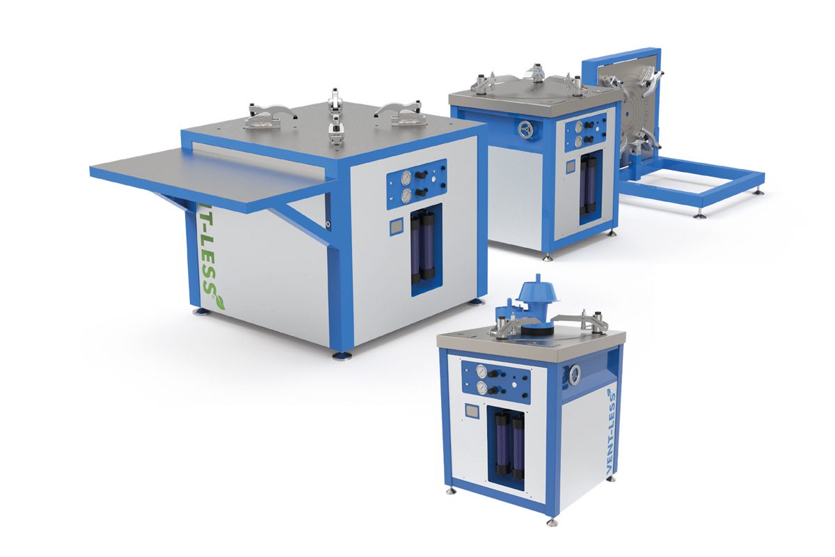
One obstacle here has been the time and expertise traditionally involved in performing the functional tests required to issue the certification. Cox has been closely involved with this work for about 25 years and more recently has worked to make some of this expertise available in the form of a fully automated test bench – a product that was announced in August 2021.
In some cases, the tests can be carried out in as little as two minutes, for something that might have required 20 minutes to perform manually, and certification can be immediately provided to a customer, incorporating a QR code.
The work is a nod to the under-appreciated complexity of breather valves, and this attempt to deliver some of Assentech’s expertise and existing data on valve testing, in an automated format, does seem ground-breaking.
The effectiveness of the approach is underpinned by the use of novel software techniques like AI and neural networks, to yield insight into how well a valve performs – this computation typically being performed in a laptop running nearby, and connected to the test hardware.
In practice, a technician or whoever is running a test will place the valve on the test bench, and enter details like the serial number or model on a laptop. To meet the requirements of a standard like API2000, a test will normally begin by measuring the set point of the valve (i.e. the pressure which opens it), a value that is determined by the maximum allowable working pressure (MAWP).
A subsequent leak test then determines how efficiently the valve retains its pressure when a carefully controlled air flow (determined by the size of the valve, and typically 0.5ft3 per hour) is passed through it. The test result has to exceed 75% of the set point pressure.
For a PVRV, the test certificate will provide the results of these tests for both ports.
A third test – not included in the standards but sometimes desirable – is a volume leak test, which will determine the volume of vapour leakage at a pre-determined tank pressure such as 75%, 90% or the operator chosen pressure (preferably the conditions under which most customers operate tanks).
This volumetric test is one part of the procedure where the proprietary AI software working under the bonnet will come into play. For example, it can automatically determine the value of the set point.
The value determined by this volumetric tests can be used to calculate the volume of vapour lost over the course of a year, which can be incorporated in calculations of the carbon footprint of the system, which many customers will want to have for ESG purposes.
With the use of neural networks, the system also learns incrementally – in practice this might mean a valve that has previously been tested will be recognised by the system automatically and subsequent tests might be performed more rapidly than before, taking two minutes rather than five.
Oddly enough, we can often determine the manufacturer of a valve purely from its performance curve says Cox.
The test bench comes in two formats: a compact, lightweight mobile unit that can be lifted into a van, and a static, workshop bench-based unit. The mobile unit can test tank breather vents from 2″ to 12″ (with an extension option up to 24″ valves) and the static 2″ to 30″.
Drilling down
The test provide a documented pathway for recording the performance of operators tank venting equipment. “This will provide evidence that they are following best practice In the Industry and satisfy the needs of the regulators,” says Cox.
Cox is optimistic that this might even help drive innovation on the component manufacturing side. For example, if innovation is forthcoming that will allow valves to better satisfy the design goal of remaining completely closed until the highest possible pressure before the set point is reached, then Cox says the group is only to happy to be able to stimulate that.