


Lowering maintenance costs and extending wastewater treatment pump product life is a key concern of any operator. Here, NETZSCH Pumps reviews some design considerations that contribute to lowering costs for progressing cavity pumps in wastewater treatment plant applications, including speed, drive configuration, sealing options, joint types, and piping systems. The article also discusses pump configuration options that can contribute to cost reductions or minimize maintenance.
WWTW pumps: Design is fundamental to controlling costs
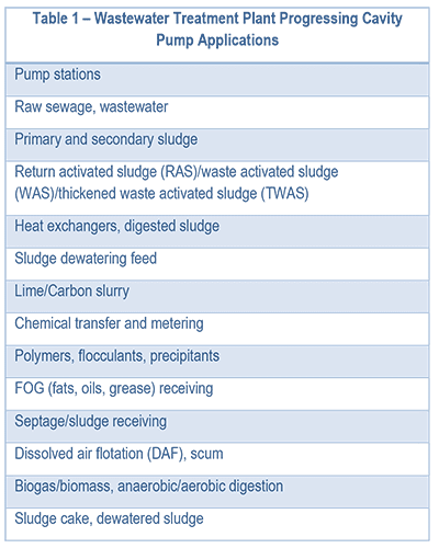
Table 1 is a summary of the wide variety of potential wastewater treatment plant pump applications.
Picking the right design for the specific application is critical for ensuring the pump (and the overall system) is going to operate properly. This will in turn be the major influence on the overall cost of ownership (COO).
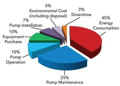
Much of the cost is determined by the initial system design and pump technology selected. A common rule of thumb suggests that about 80 percent of overall equipment life costs (maintenance, operation, and energy consumption) has to do with the initial design of the overall plant and process equipment, and the pumps used. In other words, whatever is designed comes with a set amount of fixed costs. So, selecting the right equipment (in terms of size, technology and features) will have a major effect on costs; selecting the wrong equipment will result in higher costs and more downtime. Another 10 percent goes to environmental costs (disposal), installation, and downtime. This leaves approximately 10% for the initial purchase of the pump.
There are several progressing cavity (PC) pump configurations that can be used for these applications. Each has advantages and disadvantages, and some are more appropriate than others for a particular application. PC pumps can run a long time without service, but when needed, the service required can depend on the design and options selected for the pump. Joints, access windows, type of seal, stator design, rotor materials and coatings, bearings, and ancillary equipment around the pump impact service. Ultimately the pump needs to be designed for minimal and easy servicing.
When one examines the total cost of ownership, including the initial cost of purchase, the electricity used, parts, and maintenance, what looks like a lower cost option may actually end up being the higher cost option. Reduction of service frequency, reduction of required pump parts, and easier, faster serviceability are critical attributes for pump selection. Focusing on these particular areas and spending a little bit more money upfront, will pay dividends.
Pump design considerations
Most operators will work in collaboration with an engineering firm to select and size the right equipment. Keeping in mind that the correct design is important for reducing costs, operators should consider the following factors when selecting a PC pump. Each one has its own positive and negative impact.
• Speed: The faster you run the pump, the faster it will wear and the more frequently service will be needed. In other words, greater speed = exponential wear. However, a fast pump usually means a smaller footprint and lower upfront cost (but you pay on the back end with more repairs). Slower is usually better for most applications.
• Drive configuration (with bearing frame or direct drive): The key issue is how much space is available for the pump. PC pumps are long in nature. Adding a bearing frame adds more length, but provides a robust drive shaft supported by independent bearings to handle the thrust load of the pump. This is the force (axial load) pushing the opposite direction from flow across the centerline of the pump. This is essentially what the pump undergoes as it pumps against the system backpressure. Whereas the direct drive is shorter and is sufficient for many applications.
Typically bearing frames are used when the need for high pressures exceeds direct drive capabilities, when the desire for easier servicing is required, or when a belt configuration for space restraints is preferred. Piggyback/overhead or L-shaped bases can shorten the installation footprint. Vertical mounting of the pump can also accommodate limited space.
• Viscosity: The thickness of fluid limits the pump speed, suction, discharge piping ID, and pipe length from the pump by significantly influencing the design and the pressure losses of the system. This affects the suction side or the NPSHa (Net Positive Suction Head available) for the pump. Pumps have a specific amount of head pressure required to operate correctly. Otherwise, the result is cavitation and potential failures.
• Pump rotor and stator geometry: For the most part, two geometries dominate the various applications. For simplicity’s sake, we will call them low flow/high pressure and low pressure/high flow. Both have their own inherent ratings for NPSHr (Net Positive Suction Head required) based on the pump’s internal design. There are other geometries that can provide higher flow at higher pressures and another for higher flow at lower pressures. Typically, you trade off flow for pressure and vice versa.
• Number of stages: The maximum discharge pressure and ultimately the pump rating per stage is determined by the number of stages. Typically, each stage is rated for 90 psi (6 bar). Therefore, 2 stages would be rated for 180 psi (12 bar) and so on. Adding more stages for a given rated pressure divides the pressure affecting each stage. More stages equals lower pressure per stage and allows for longer life. With most applications in WWTPs, there is abrasion. Abrasion comes from grit and other inorganics (as well as some organics), that cause wear over time on the pumping elements. This wear is to be expected; it is normal to de-rate the pressure per stage due to the amount of anticipated wear. For example, pumping polymer is very lubricating, has no abrasion factor, and can be rated for the maximum capability of the pump. As another example, 1-2% sludge may only be derated by 20% per stage (90 psi x 80% = ~70 psi) making the rated discharge pressure 70 psi or less. Finally, if you were to pump cake (20% or higher), each stage would need to be derated to 50% or more.
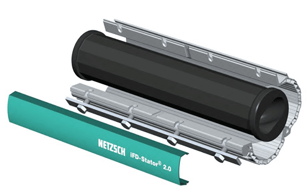
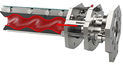
• Stator design: The design of the stator can help facilitate faster and easier replacement. Each stator inherently uses compressive forces in the design that compresses around the outside of the rotor; which in turn creates the sealing line of the pumping elements. These compressive forces are what make the pump work. However, they also make it harder and more time consuming to replace the stator with a new one. A new stator requires a great amount of force to install. NETZSCH offers a time-saving stator replacement option. The iFD-Stator® design allows for the compressive forces to be released/removed during installation (and removal). Unbolting the compressive shell releases the axial and radial compression of the stator on the rotor. This allows for the new stator tube to slide on with relative ease and then be clamped down without the need for extra turning forces. See Figure 2.
Money-saving stator adjustments can also compensate for wear, using compression to re-establish the stator sealing line, increasing operational life and bringing the stator back to factory performance. The process can extend stator life by up to six times. This is a boon to operators, who would otherwise have to take the pump out of service, shut down the entire process, and lose all the revenue from that train. While standard stator replacement may take as much as 6 hours, with the NETZSCH xLC® (stator adjustment device) attached to a pump, it takes less than 2 minutes (while pumping or not) for the stator to be easily adjusted or tightened to renew the performance back to factory standards. See Figures 3 and 4.
• Materials of construction compatibility: Are important to ensure long life, abrasion resistance, temperature, and resistance to upset conditions. For example……
• Polymers, neat vs blended: Neat polymer requires a specific construction to ensure the rubber does not swell (swelling causes excessive compression and premature failure). This typically requires FKM/FPM elastomers with 316SS construction. Whereas made-down polymer can use Buna and carbon steel.
• Ethylene propylene diene terpolymer (EPDM) avoidance: EPDM is not compatible with oils. This should not be used for typical municipal sludge.
• Corrosion: This is normally seen as a chemical attack. It can be an acidic or a base. It eats away at the material or can cause swelling or detrition of the materials, resulting in premature failure.
• Hardness: This attribute helps to promote long life. Typically the harder the materials for rotors, the longer they will last. However the same cannot be said for stators. Sometimes having a softer stator (<60 Shore A durometer), can extend life when pumping very abrasive particles.
• Temperature: It can cause the elastomers to expand resulting in excessive compression or, on the opposite side, shrinkage due to the cold. This will reduce compression of the stator on the rotor resulting in more slip, lower flow or inability to pump against the back pressure of the system. With freezing temperatures, if the fluid is frozen, cast iron castings could crack.
• Adding rotor coatings for increased hardness: Tungsten carbide coatings will make the rotor last 3 to 4 times longer. Re-chroming to add a new layer to the worn rotor is another option and while it is significantly less costly than the rotor coating, it is not recommended. Re-chroming may add a new layer, but the plating is not equally deposited and does not renew to factory tolerances. It also creates high points or low points to the rotor diameter; it does not restore the original diameter. This reduces stator life and may affect pump performance.
• Percent solids: This determines how fast the pump can run and impacts pump configuration. It ultimately dictates the viscosity of the fluid being pumped. Water-like sludges (2% or less), present few limitations on a pump design. However, as the percentage increases, so do the design constraints, such as: mechanical seal, max rpm, motor size, wear resistance, geometry configuration, suction pressure, piping layout, and ancillary equipment.
• Fluid media size (particle and ball sizes): Every pump has a maximum particle size it can handle. When it comes to PC pumps, there are two considerations: particle size and max “ball size”. The particle size relates to the amount of particles and average size of particles in the fluid. The max ball size is the largest soft size particle the pump can handle which is typically 80% of the rotor diameter.
• Type of shaft seal and seal water/flushing options: This is always a highly debated topic. With many options, multiple seal manufacturers, and a wide range of applications, each fluid being pumped has certain requirements, each with pros and cons. Depending on the application the design may require packing, single component seal, cartridge seal, double seal, or some new style of seal. It is best to consult with seal and pump manufacturers for the best solution for your process.
There are a variety of shaft seals for different applications and care must be taken to get the right one for the application. Depending on the seal there may be a complex seal plan that must deliver water or fluid to the seal to ensure it operates properly. Otherwise, operators run the risk of the added expense associated with maintenance to pull the pump apart to get access to the seal – the last piece in the pump. Here are some examples that may not fit every application: wastewater to thin sludges (<6 percent) with or without quench or flush could use single slurry seals with a knife edge, encapsulated component, or a standard single mechanical seal, either a cartridge or component. Thick sludges (6 to 10 percent) with quench and/or flush can use single slurry seals, single inverted slurry seal, double mechanical seals, or packing. Cake calls for packing, double seals (>10 percent) with quench and/or flush, double mechanical, or packing. Neat polymer or made-down/mixed emulsion polymer should use single slurry seals, standard single mechanical seals, or packing, while made-down/mixed/emulsion polymer should opt for single slurry seals or standard single mechanical seals.
• Correct joint type for application along with the right joint options: The joint to be used depends on the pump size, loading, and operation. For smaller pumps, pin joints are adequate. Pin joint longevity can be increased, however, with a double-sealed joint option or the covered-seal joint option which protects against abrasion and sharp objects but, for larger pumps, additional joint options are available.
Pumps that will operate with many stops and starts may function more effectively with a gear joint. Double sealed, oil filled gear joints are preferable to those using grease; oil refills and replenishes itself, whereas grease, once pushed out, does not replenish. This makes for a more robust, long life joint, that will tolerate frequent stops and starts (>3-4 starts/hour).
• Joint angularity: This is the distance between the joints. Increased joint distance provides a longer joint life. Three forces impact joints: axial (X), shear/bending (Y), and rotational (torque). Higher angularity (Y-axis forces) means less joint life. While you do not want too long a pump, one with a longer joint distance will last longer.
• Suction lift requirements, up to 30 feet (ftwc – feet water column): It is common to have suction life requirements for WWTP applications. PC pumps work great for suction lift. However, there are some tricks for ensuring the pump is set up correctly to perform as intended. Having the wrong setup can cause the pump to not work properly or to fail. Consult with your pump manufacturer on their recommendations for suction lift.
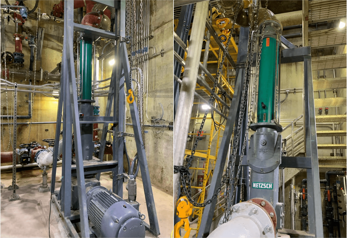
• Pump orientation (horizontal, vertical, wall mount, upside down, etc.): The pump orientation can make all the difference for operational longevity, space saving or for simplifying the piping layout. PC pumps can be positioned in many ways. With PC pumps being inherently long due to the design, it is possible and becoming more prevalent to install them vertically as older plants make upgrades with limited room in the existing buildings. This saves space and preserves the benefits and capability of using a PC pump.
Pump serviceability
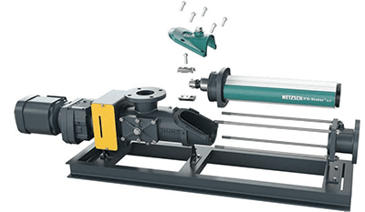
Pump servicing in place: Most pump manufacturers offer a full service-in-place (FSIP®) option without needing any additional footprint in the often space-constrained process line. In this case the rotor, stator, and mechanical seal can be removed without the need to remove suction or discharge piping, drive, or electrical components. Some can even upgrade existing installed pumps; however, flow and pressure reductions may apply. This can be a time-saving alternative to standard servicing, which may require removing piping to get the space needed to service the pumps, as well as unbolting numerous components to take the stator off, and even calling in an electrician to remove electrical components to access the pump for servicing. See Figure 6.
Piping systems and accessories
The system design should consider these piping system factors:
• Suction side liquid trap for priming
• Large pipe inner dimensions (IDs) to reduce friction losses
• Long Radius Elbows
• Reduce suction and discharge pipe lengths as much as possible
• A discharge check valve
• Expansion joints
• Avoid pipe stress on pump
• Some form of pressure relief, for example a pressure relief valve (PRV), pressure switch, or burst disc
Pump protection
Pump design should include consideration of stator dry run protection, choice of motor thermostats, flowmeter, variable frequency drive (VFD) or over-current. The pump should be designed to avoid cavitation and should include pressure gauges for suction and discharge and isolation from process fluid.
Optimizing pump design for cost-efficiency and longevity
The design of progressing cavity pumps plays a crucial role in controlling maintenance costs and extending product life in wastewater treatment plant applications. By carefully considering key design elements such as speed, drive configuration, sealing options, joint types, and piping systems, operators can make informed decisions that contribute to cost reductions and minimize downtime. Also, selecting the right equipment and implementing money-saving strategies post-installation can further enhance the efficiency and longevity of pump systems. Ultimately, a well-thought-out design benefits the immediate operation and ensures long-term cost-effectiveness and reliability.