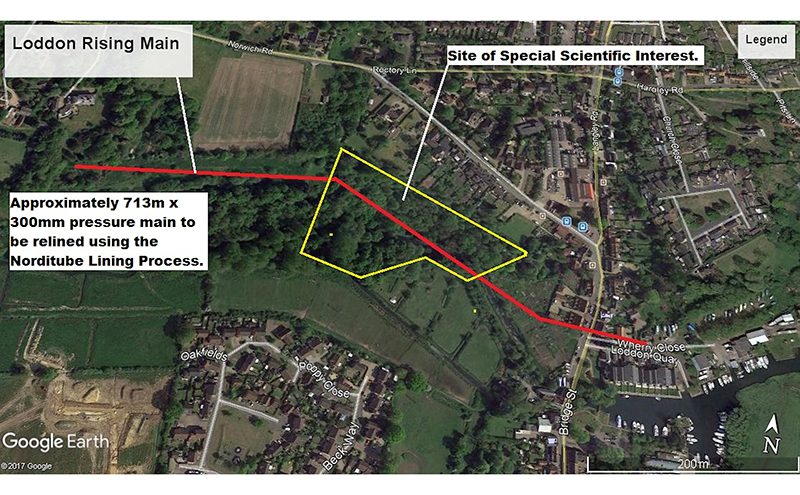
The Loddon Sewer Rehabilitation scheme (in London) for Anglian Water was designed to enable the repair of a 300mm diameter rising main that had experienced multiple bursts. Water and wastewater asset management firm Onsite was engaged to provide a solution, the details of which are presented in this article

One major complication for the proposed rehabilitation was that part of the route of the rising main runs through a site of special scientific interest (SSSI). This means an open-cut solution cannot even be considered. Access to the pipeline also looked difficult. Anglian Water met with Onsite and Claret Civil Engineering (the civils contractor) to discuss the available options and target the problematic areas of the route.
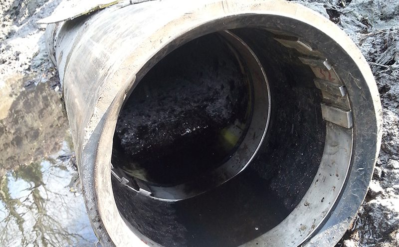
Since the existing host pipe had failed on multiple occasions it was clear that any solution needed to provide a standalone result, one that did not require the host pipe to be part of the final structure. Also, the lining had to be designed for an internal operating pressure of no more than 5 bar.
Planning
The length of rising to be rehabilitated ran between a pumping station and a collection point: 713m of 300mm diameter pipe. Usefully, alongside the existing rising main was a redundant rising main that was installed as a backup pipeline. This was used to manage the rising main flows for the duration of the lining activity and meant flows could quite easily be switched over at the pumping station.
Getting the right liner material was a priority, and Onsite plumped for the NORDIPIPE™ system from Austria-based NordiTube Technologies SE, seemingly its first UK deployment. NORDIPIPE™ is flexible and quick to install, so it can be used to rehabilitate many kinds of pipes (steel, ductile and cast iron, asbestos cement, concrete, PVC, and PE). Moreover, it can be used to reline both partially and fully deteriorated pipes and often pipes with bends and deflections. It is also a strong liner able to withstand not only the internal pressure, but also external pressure resulting from hydrostatic, soil and live load situations.
Installation
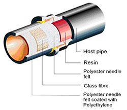
The NORDIPIPE™ liner for Loddon consists of a combination of a coated felt, two glass-fibre layers and an additional layer of felt. The glass-fibre layers in the liner have excellent characteristics when in tension, making for a very strong and flexible liner. It has its own intrinsic strength and stiffness and therefore does not rely on the host pipe for structural support, though it needs to be in close contact with the host pipe to maximise the final lined pipe’s cross-section, and to enable the ends to be sealed off properly.
Before the liner is impregnated, the correct liner length needs to be determined. The line length has to be measured and transmitted from the site to the impregnation facility including any turn-back required to get to the face of the host pipe.
At the impregnation facility, the liner has to be sealed off at both ends. A vacuum is applied at the end where the resin is to be poured into the liner. The right amount of resin and hardener is then mixed and poured into the liner.
The resin plug is then allowed to run inside the liner. The liner is then pinched between the roll bars of the impregnation bed and the liner is slowly drawn through the rollers ensuring complete saturation of the liner material layers. As the liner comes off the bed it is submerged into an ice bath to slow down the curing of the resin. The liner is then pulled into the refrigerated vehicle with ice being introduced between each stacked layer. The refrigerated vehicle is then driven to site.
For the installation of the liner at Loddon, Onsite chose an air inversion with a steam cure method as this is a relatively easy and cost effective way of installing the liner.
The refrigeration vehicle doors are opened and the liner is wound into an inversion drum. The end of the liner is closed and attached to a hold back rope/strap that is wound onto the spindle of the turning unit in the inversion drum. The spindle is wound so that the liner is taken up onto the drum. When the liner is fully wound onto the spindle, the front part of the liner (where the vacuum system was previously attached) is then connected to the inversion cone. If the liner has a pull-strap, it has to be retrieved and brought through the opening of the cone. When all of the liner is wound into the inversion drum, the cone is fastened to the drum. The drum is then pressurised allowing the liner to be forced out under control through a protective support which then leads to the host pipe. The drum maintains constant air pressure allowing the liner to invert through the host pipe until it reaches the termination point.
Steam curing
After the liner has been inverted through the host pipe to the termination point, vent tubes are attached to the exposed end of the liner to enable the release of hot air/steam from the liner. The vent tubes are typically fitted with a valve and a hose coupling and a hose leads from the vent tube up to ground or street level to act as a muffler. The valves either on the vent tubes or at the muffler control the volume of air and/or air-steam flow and therefore the pressure inside the liner. A small steam condensate drain hole is punctured through the liner at a low point (underside) of the exposed liner to expel any accumulated condensate collecting at the liner tail.

Steam is then introduced at the steam generation station which is connected through the inversion drum along with a proper flow of air. This is released at the exhaust station to achieve an even distribution of heat over the length of the liner in the pipe. The proper boiler size and the proper air compressor size are determined from the diameter, length and thickness of the liner, and to some extent upon the temperature of the soil around the host pipe.
With the steam being applied, the resin in the liner starts the curing process with steam at temperatures as high as 100ºC (212ºF). This is generally held for around 4 hours after which the liner is allowed to cool until both ends are below 40ºC.
The steam pipes are removed and the pipe can be cut back to the nominal face of the host pipe. The end sealing mechanisms are then installed.
The end seals prevent water from migrating along any annular gap that may exist between the NORDIPIPE™ liner and the host pipe. This may be particularly important if there is to be a hydrostatic pressure test performed upon the installed liner. In non-potable applications, such as force mains or applications with some particulate content, an end treatment prevents damage on a long-term basis due to abrasion or wears on the liner-end and establishes a smooth transmission between the host pipe and the liner.
For the Loddon project OnSite has used Weko seals to provide a firm seal against the host pipe with the lined length then being coupled to the remainder of the pipeline using Viking Johnson fittings.
The Loddon Project was managed, resourced and delivered by Onsite’s Senior Engineer, Scott Weston, who programmed, in conjunction with the civil contractor (Claret Civil Engineering) and the lining team, the enabling works, liner impregnation, delivery and installation of five individual liner installations which was completed in three weeks. Following testing, the pipeline went back into service a few weeks later.